(This information can also be found in a printable format in the Brochures section of this website).
1. Calibration
The purpose of calibrating your wash rig is to ensure that the flow rate through the engine wash probes is in accordance with the relevant AMM for the engine being washed.
During normal operation of the rig you should be regularly monitoring flow rate using the sight glass fitted to the tanks and timing the wash. If you find you are not achieving the required rate, then the pressure gauges might need calibrating, or you may have a blockage in the filter.
• Calibrating the pressure gauges
Should the pressure gauges need calibrating, or updated Quality Assurance Certification be required, remove the gauges from the rig and test their accuracy using a test pump fitted with a certified test pressure gauge (It is important that any test gauge used is annually calibrated to the appropriate national standard of the country of use). If testing is not possible, or any gauge proves to be faulty, new calibrated gauges complete with replacement fibre washers can be ordered from Juniper (Part No. SM709).
Important note: If you have to remove the gauges, take careful note of their position and make sure they are replaced in exactly the same position on the operational side of the rig (so that the gauge and sight glass can be viewed from the same position). A new fibre washer may be required between the gauge adaptor and the tank body to achieve the correct positioning.
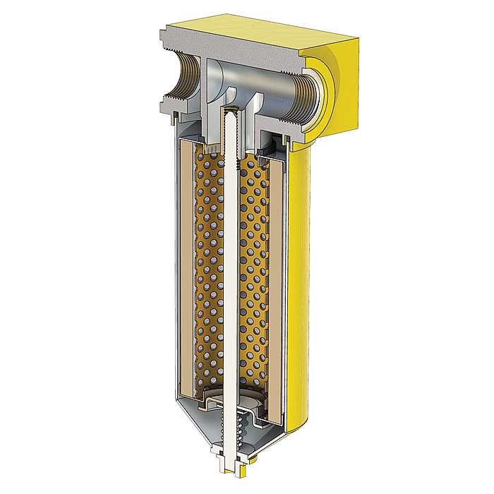
• Cleaning the filter
Clean the stainless steel filter element by removing it from it's housing, cleaning in kerosene and finally rinsing in water before re-assembling. (Please refer to the maintenance section your rig's manual if you need any guidance with this). If the filter element is damaged, a new one can be ordered from Juniper (Part No. JMP/STD/B/5648).
2. Fluid vessel pressure testing.
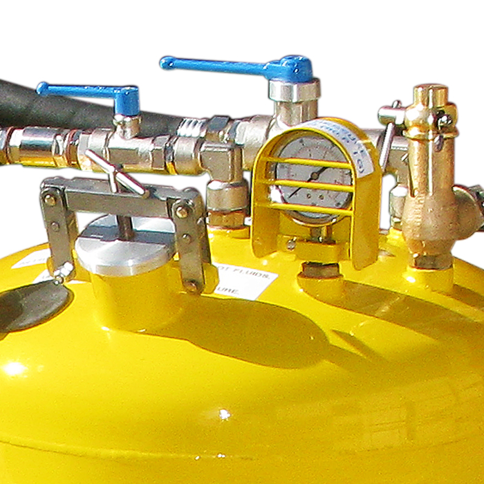
When the rig is assembled we pressure test the fluid vessels by connecting a hydraulic test water pump to one of the top connections and blanking off all the other connections. The pressure is then raised to 1 1/2 times the normal working pressure (120 PSI) and left on test for 1 hour. During this time there should be no leaks or distortion. (Leaks can be easily detected by brushing a soapy solution around any of the tank fittings).
If your Health and Safety Department requires you to perform your own pressure test, or for any other reason you need to test the integrity of the pressure vessel, then this can be done easily without removing the pressure vessel from the rig's frame.
We suggest you remove the pressure relief valve and fit a delivery hose from a hydraulic test pump to the connection. With all ball valves in the closed position, raise the pressure to 120 PSI and check for leaks and loss of pressure as outlined previously.
Important Safety Note: If the pressure gauges fitted to your rig are set at 0-100 PSI, these must be removed and the connection holes blanked.
3. Maintenance of the high pressure system.
It is important in prolonging the active life of the rig's high pressure system that the rig is completely de-pressurised after use and not stored for any length of time with the fluid tanks pressurised.
To relieve all pressure in the system (so that the pressure gauges read zero), firstly turn the nitrogen cylinders off (turning the hand wheels fully clockwise), then close the high pressure regulator (turning the knob fully anti-clockwise).
Ensuring that the tank filler caps are closed (hand tight) and all ball valves are in the closed position (across the direction of flow), open both the nitrogen inlet valves to each tank and relieve any pressure in the tanks using the release levers on the pressure relief valves.
Finally, open the high pressure regulator knob slightly, just enough to relieve the indicated nitrogen pressure reading on the right hand gauge of the regulator, then close the knob fully anti-clockwise.
4. The High Pressure regulator
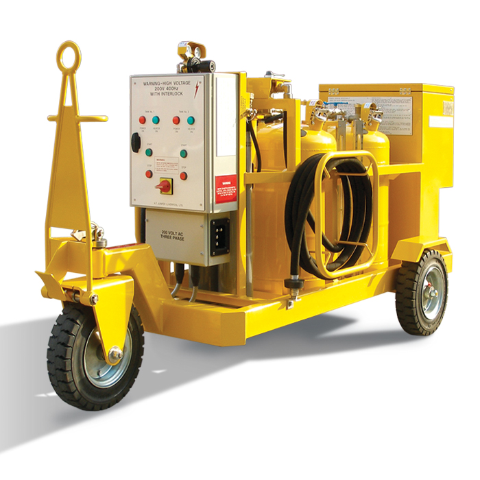
The gauges fitted to the High Pressure Regulator on the Juniper 2 x 25 and
2 x 50 Gallon Compressor Washing Rigs indicate the nominal pressure of the input from the Nitrogen Cylinders and a nominal regulated output pressure. This output pressure is then directed to the fluid tanks which have calibrated gauges fitted. These gauges measure the regulated pressure in the tanks and it is this regulated pressure which determine the fluid outlet from the tanks to the set of washing probes fitted to the engine.
There is no necessity for the gauges on the HP Regulator to be calibrated as they DO NOT effect the performance of the rig.
For Health and Safety reasons, and to comply with EU regulations the gauges MUST NOT be removed. If they are removed the Warranty of the Regulator will be not be valid.
If a new regulator is required a Certificate of Conformity will be supplied with the regulator. Calibration certificates for the gauges fitted to the regulator will not be supplied.
5. Testing the immersion heaters.
To evaluate the insulation integrity of the heaters, connect an insulation tester to the heater element and an earth point on the heater case. Permissible readings should be between 2 and 1000 mega-ohms.
6. Inspection and testing of nitrogen cylinders
The BSI, in Annex B to EN 1968:2002, gives the following recommendations for the inspection of compressed gas cylinders:
1. Ar, N2, He, H2, Air, O2
Normative intervals: period - 10 years
(These intervals conform to the 1999 edition of RID/ADR)
Informative recommendations for next revision of ADR: period - 10 years
However, as we have removed the non-residual valve on cylinders supplied with our rigs to facilitate charging, we recommend a visual test every 5 years and a full inspection every 10 years.