Juniper

A.T. Juniper (Liverpool) Ltd
Marshall Works
5-17 Bleasdale Road
Allerton
Liverpool
L18 5JB

Tel: +44 (0) 151 733 1553
Fax: +44 (0) 151 734 3166

Also at:
Ash House, Prenton Way
North Cheshire Trading Estate
Prenton, Wirral
England CH43 3DU

All mail to the
Liverpool address only.

Contractor Cage Code:
U2066

Juniper now deals with 530 customers worldwide

JMP/CFM56/D/4777/C200

JMP/CFM56/D/4777/C200
NSN 1730-99-668-7936

SPECIFICATION

Size: (L) 2515mm x (W) 1067mm x (H) 1296mm   Weight: (Dry) 352Kg
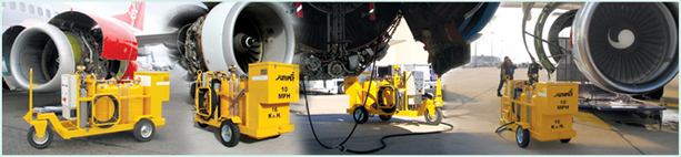
Packing crate dimensions: (L) 2642mm x (W) 1093mm x (H) 1524mm  Weight: (Gross) 601Kg

INTRODUCTION


The 2 x 25 gallon multi-engine compressor wash rig (JMP/CFM56/D/4777/C200) comprises two 
115 litre stainless steel pressure vessels mounted on a rigid steel chassis, supported by three heavy 
duty wheels with 16” super elastic tyres, one of which is mounted on a heavy duty steering castor unit. 
A drawbar, which can be locked in the upright position for storage and safety, is attached to the 
steering castor unit with a drawbar operated parking brake acting on the front wheel when locked in 
the upright position. 
 
Each tank is fitted with a filler cap, gauze strainer, pressure gauge, sight glass, pressure relief valve, 
3/4” BSP drain valve and a 6kW immersion heater.
 
A 3/4”, 20 ft long, outlet delivery hose is stowed on the right side of the rig as viewed from the front, 
with a 1/2”, 20 ft long, outlet delivery hose, together with a 1/4”, 20 ft long blow-off hose in the rear 
storage box for clearing the sensing tubes/hoses after a wash. Rubber protective collars are installed 
on the end of each hose to protect the couplings from damage.

OPERATION
 

The fluid in the tanks is pressurised by two rechargeable onboard nitrogen cylinders 

(a MS28889-2 Schrader charging valve is fitted to the rig for in-situ recharging) controlled by a 

regulator and distributed to the top of each pressure vessel via a nitrogen inlet manifold. 

There is also an optional Air Inlet Kit (JMP/CFM56/D/6612) available to enable the connection of 

offboard compressed air or nitrogen if required. Once pressurised, the fluid is forced up the outlet 

stack pipe to the appropriate fluid outlet isolation ball valve. From there it is directed through the filter, 

to the 3-way engine selection ball valve, which controls the output to the appropriate tooling via the 

outlet hose connection to the twin hose assembly.

 
The rig has two 6kW immersion heaters (one for each pressure vessel) requiring a 115V/200V, 
3-phase, 400Hz electrical power supply to heat the tanks to a temperature of 70oc in one hour. 
The necessary power is supplied from a ground power unit (GPU) or hangar power supply. 
A 24V battery installed in the rig’s electrical enclosure provides the power required for the interlock 
(necessary for the power to connect) to operate.

PRESSURE SYSTEM MAINTENANCE
 

There are routine maintenance tasks outlined in the relevant section of the operations manual,
and we are highlighting some of the most important here on the website. Click here to bring up
maintenance tips on keeping the rig's high pressure system working perfectly.

JMP/CFM56/D/4777/C200